Piezotech FC processing guide
source:未知date:2019/04/13 18:57 browse:
I - Introduction
Piezotech ® FC is a range of P(VDF-TrFE) printable electroactive polymers. After processing, (deposition, annealing, poling etc…) they exhibit pyroelectric and piezoelectric properties. Typical applications are:
● printed sensors (Pressure, temperature, Ultrasound, Infra-red),
● printed keyboards,
● printed speakers,
● printed memories,
● printed actuators
For many purposes, these polymers are used under thin film forms, obtained via printing processes with coated electrodes.
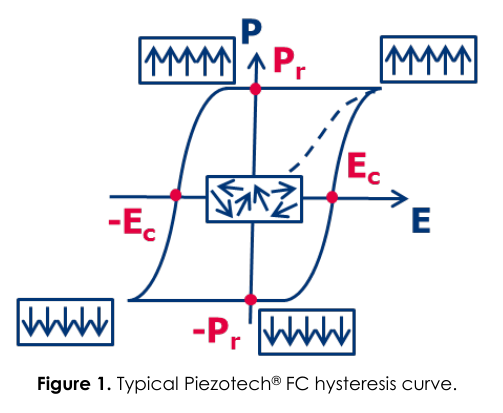
Piezotech® FC polymers are ferroelectric polymers. Figure 1 shows a typical Polarization vs Applied electric field plot for a film based on a Piezotech® FC polymer. This curve exhibits a remnant polarization (Pr) when no electric field is applied. This remnant polarization can be inverted for [E]>Ec (coercive field).
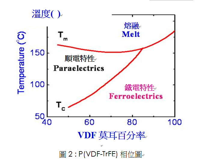
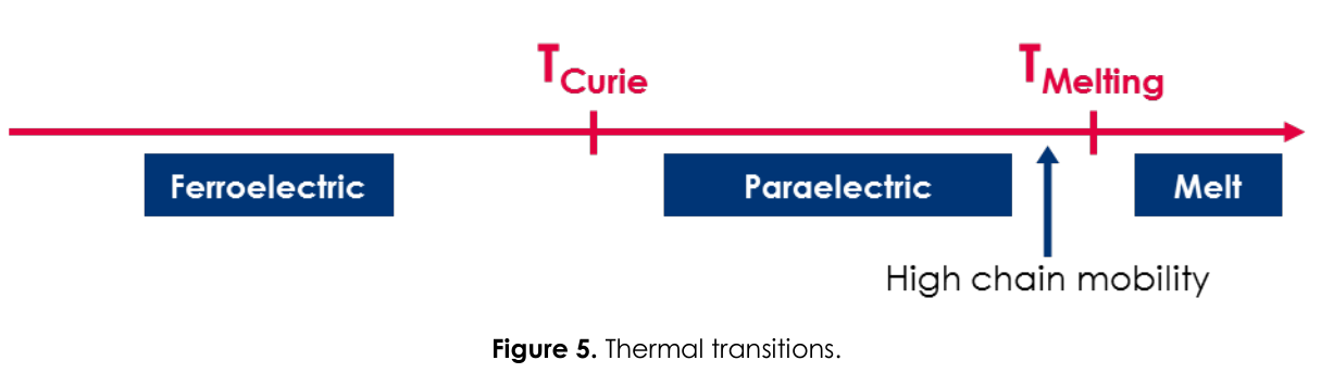
The copolymers are characterized by their Curie Transition temperature (Tc) which corresponds to the Ferroelectric to Paraelectric transition. This temperature depends on copolymer composition (see figure 2). Once poled, the polymers exhibit piezoelectric and pyroelectric properties. Typical properties for the Piezotech® FC range are given in annex 1.
II - Processing
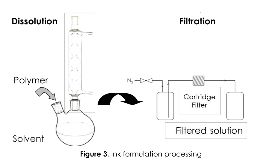
II – 1. Ink Formulation
The copolymers are soluble in different solvents given in Annex 2. The concentration of the polymer in the solvent has to be adjusted in order to get the appropriate viscosity corresponding to the printing process used. The actual ink formulation can be obtained by progressively adding the polymer into the solvent under heating. In order to get homogeneous films with high electrical breakdown a filtering step of the solution is required (ideally 1µm or less). This will remove impurities and prevent the formation of gel particles. Standard commercial filtering processes using filtering cartridges or filtering syringes are commonly used.
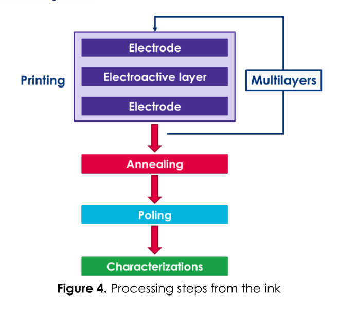
 II – 2. Processing Steps: printing and post-treatments
The ink formulation (polymer solution) can be coated via different printing processes (solvent cast, screen printing, spin-coating, ink-jet, gravure …) on a given substrate (PET, PEN, PC, glass…) under a clean atmosphere, until an homogeneous and dry film is formed.In order to avoid bubbles in the film, it is important not to use syringes during the printing process.
II – 2.1. Solvent Evaporation
In order to get rid of any residual solvent and enhance film properties, a solvent evaporation step under atmospheric pressure or under vacuum can be carried out below the solvent’s boiling-point temperature.
II – 2.2. Annealing
Annealing is a critical step to obtain the films with the best properties. It will control crystallization of the material and enhance electrical as well as mechanical properties. For this purpose, films may need to be annealed at a temperature between the Curie temperature and the onset of crystallization during a few minutes (typically 15°C below the melting point). A rapid annealing may be obtained on thin films using Infrared or Flash annealing.
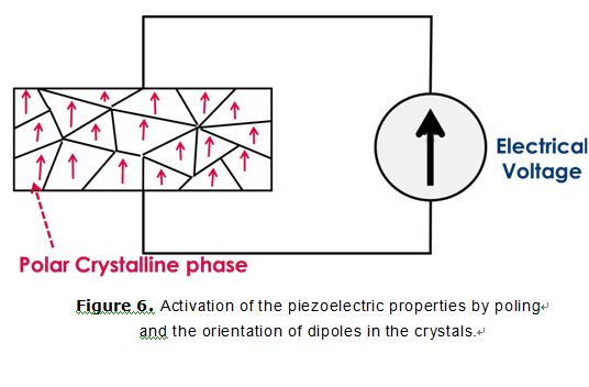
 II – 2.3. Poling
In order to activate a copolymer material, a poling step is necessary. Using an increasing low-frequency voltage, an electric field above the coercive field value (i.e. 50V/µm) has to be applied. Depending on the film thickness, its surface, and the response precision needed, different methods can be used.
The application of the electric field and the hysteresis curve characterization can be done using one of the following:
● A direct application of the electric field through the electrodes with a voltage generator (in this case there is no measurement of the induced electrical polarization (charge displacement))
● A Sawyer-Tower circuit (electrical charges measurement, hysteresis curve)
● A ferroelectric tester (i.e.., Precision MultiFerroelectric Radiant Technology) with an external amplifier if a high electric field is needed (depending on the film thickness)
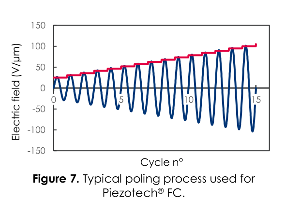
When a voltage generator is coupled with a signal generator, the electric field can be applied according to the following parameters:
● Number of cycles to reach Emax: 15
● Frequency: 0,05Hz (higher is possible)
● Signal: sinusoidal
● - Emax > 2Ec
● - Typically Emax=100V/µm
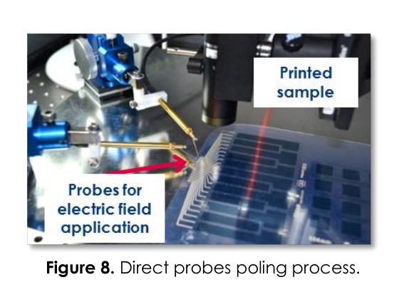
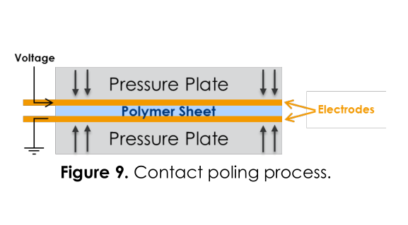
For printed devices (mainly thin layers), the poling electric field can be applied directly through the film electrodes by using a direct probes contact system (figure 8). For non-printed films (thick layers), poling can be done through contacting and pressing the film between two electrodes (figure 9). For large surfaces, a Corona poling can be used.
III - Driving & Measurements
III – 1. Deformation under an electric field
The deformation caused by the applied electric field can be defined by the simple formula:
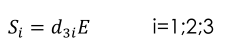
Where
● represents the strain (relative deformation) of the sample in the xi direction
● d31 is the piezoelectric strain constant (in a perpendicular direction with respect to that of the applied electric field)
Example of an element with the following characteristics:
Length: l=1cm
Width: w=2mm
Thickness: t=9µm
Applied voltage: V=200V -> E (electric field) = V/t
(d31, d32, d33) = (11, 10, -30) pC/N

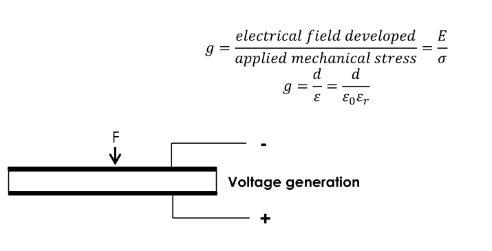
III – 2. Sensors: Orders of Magnitude, Voltage Generation
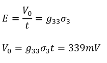
The electric field output (E) caused by an applied force can be defined by:

Where:
● σi is the applied mechanical stress (N/m²)
● gij is the piezoelectric voltage constant (Vm/Nm²)
Example of an element with the following characteristics:
Length: l=2cm
Width: w=2cm
Thickness: t=100µm
(g31, g32, g33) = (216, 19, -339) *10-3 - Vm/Nm²
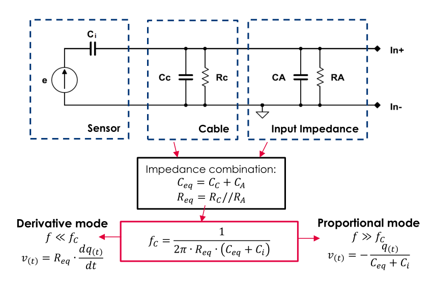
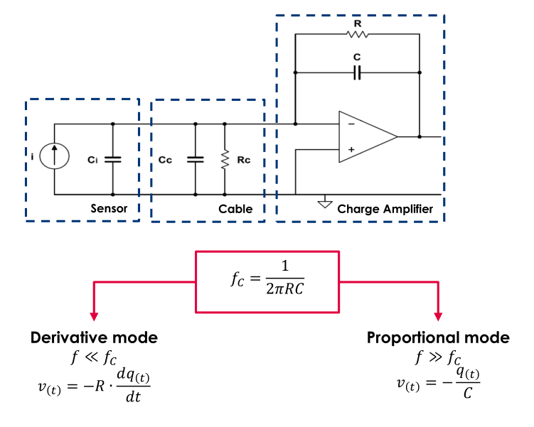
III – 3. Signal Measurement
The piezo sensor is stimulated with a given mechanical stress and frequency (f) which generates charges (q). The voltage read (vt) can likewise be proportional to the stress. The limit between the proportional and derivative modes is delimited by the cut-off frequency (fc). By directly connecting a sensor to a DAC (Data Acquisition Card), Oscilloscope, the measurements are dependent of external impedances (sensor capacity, cable losses, oscilloscope probe…) but their influence can be minimized by using a charge amplifier.
Direct connection
Use of a Charge amplifier:
Annex 1: Typical properties for the Piezotech ® FC & Piezotech ® RT range
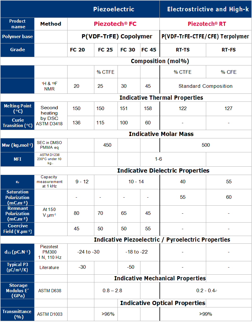
Constants are given as indicative value, it depends strongly on processing conditions (annealing & poling) and on temperature
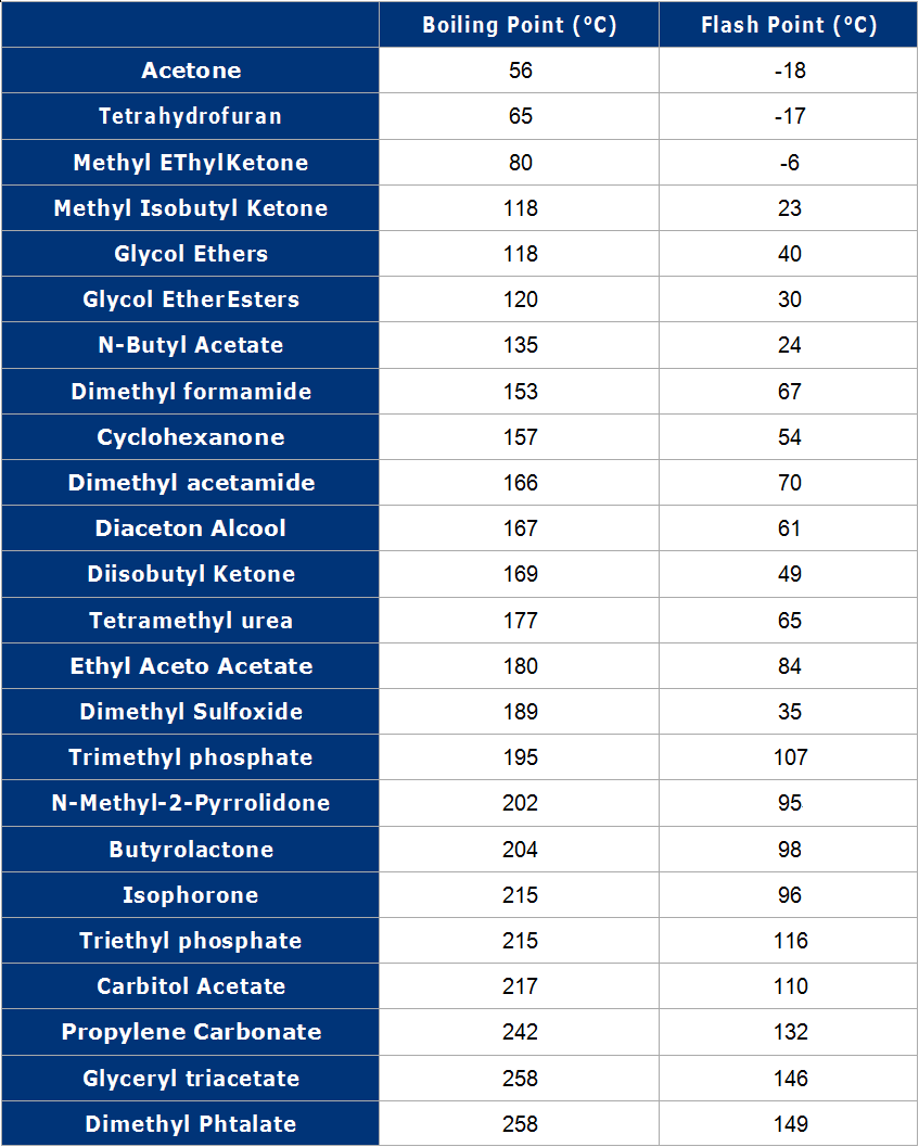
Annex 2: Piezotech® FC/RT solvents
Indicative list of solvents that can be used to dissolve & formulate Piezotech FC® and Piezotech® RT polymers solvent